
Page 887 - Rollingbearings
P. 887
Design considerations
Design Raceways on shafts
considerations and in housings
• should have the same hardness, surface
Abutment inish and axial run-out as a bearing
dimensions washer, if the load carrying capacity of a
cylindrical roller and cage thrust assembly
is to be fully exploited
Abutment dimensions should fulil the • should be designed using the dimensions
following: E and E (product table, page 888),
a
b
which take radial displacement of the
• Support surfaces in housings and on roller set into consideration
shafts should be at right angles to the
shaft axis and provide uninterrupted For additional information, refer to Raceways
support over the entire washer face. on shafts and in housings, page 179.
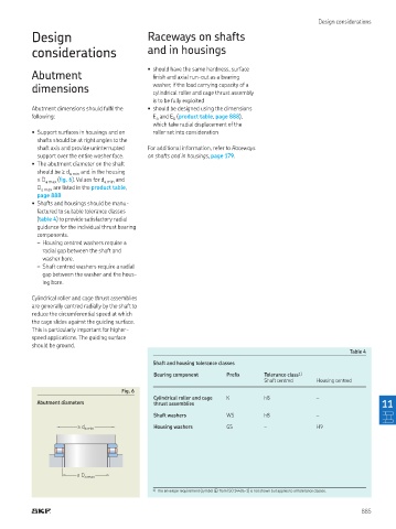
• The abutment diameter on the shaft
should be ≥ d a min and in the housing
≤ D a max (ig. 6). Values for d a min and
D a max are listed in the product table,
page 888
• Shafts and housings should be manu-
factured to suitable tolerance classes
(table 4) to provide satisfactory radial
guidance for the individual thrust bearing
components.
– Housing centred washers require a
radial gap between the shaft and
washer bore.
– Shaft centred washers require a radial
gap between the washer and the hous-
ing bore.
Cylindrical roller and cage thrust assemblies
are generally centred radially by the shaft to
reduce the circumferential speed at which
the cage slides against the guiding surface.
This is particularly important for higher-
speed applications. The guiding surface
should be ground.
Table 4
Shaft and housing tolerance classes
Bearing component Preix Tolerance class 1)
Shaft centred Housing centred
Fig. 6
Cylindrical roller and cage K h8 –
Abutment diameters thrust assemblies 11
Shaft washers WS h8 –
Housing washers GS – H9
≥ d a min
≤ D a max
1) The envelope requirement (symbol � from ISO 14405-1) is not shown but applies to all tolerance classes.
885