
Page 577 - Rollingbearings
P. 577
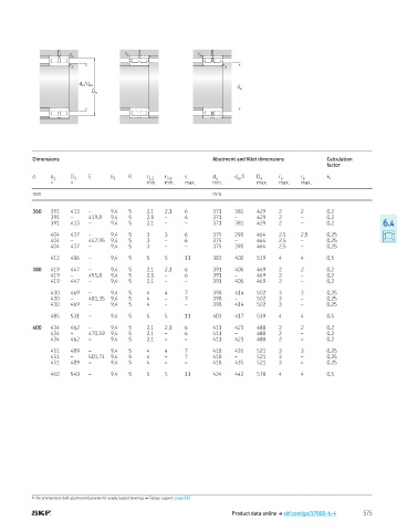
r a
                      r b                                   r a
                      r a                                           r a


                         d a  /  d as
                                                                        d a
                             D a


           Dimensions                                            Abutment and illet dimensions     Calculation
                                                                                                   factor
           d    d 1   D 1   E     b 1   K    r 1,2  r 3,4  s     d a   d 1)   D a    r a   r b     k r
                                                                        as
                ≈     ≈                      min.  min.  max.    min.         max.   max.  max.
           mm                                                    mm

           360  391   413   –     9,4   5    2,1  2,1   6        371   381    429    2     2       0,2
                391   –     419,8  9,4  5    2,1  –     6        371   –      429    2     –       0,2
                391   413   –     9,4   5    2,1  –     –        371   381    429    2     –       0,2              6.4

                404   437   –     9,4   5    3    3     6        375   390    464    2,5   2,5     0,25
                404   –     447,95  9,4  5   3    –     6        375   –      464    2,5   –       0,25
                404   437   –     9,4   5    3    –     –        375   390    464    2,5   –       0,25

                412   486   –     9,4   5    5    5     11       383   402    519    4     4       0,5

           380  419   447   –     9,4   5    2,1  2,1   6        391   405    469    2     2       0,2
                419   –     455,8  9,4  5    2,1  –     6        391   –      469    2     –       0,2
                419   447   –     9,4   5    2,1  –     –        391   405    469    2     –       0,2

                430   469   –     9,4   5    4    4     7        398   414    502    3     3       0,25
                430   –     481,35  9,4  5   4    –     7        398   –      502    3     –       0,25
                430   469   –     9,4   5    4    –     –        398   414    502    3     –       0,25

                485   531   –     9,4   5    5    5     11       403   417    539    4     4       0,5

           400  434   462   –     9,4   5    2,1  2,1   6        411   423    488    2     2       0,2
                434   –     470,59  9,4  5   2,1  –     6        411   –      488    2     –       0,2
                434   462   –     9,4   5    2,1  –     –        411   423    488    2     –       0,2

                451   489   –     9,4   5    4    4     7        418   435    521    3     3       0,25
                451   –     501,74  9,4  5   4    –     7        418   –      521    3     –       0,25
                451   489   –     9,4   5    4    –     –        418   435    521    3     –       0,25

                460   540   –     9,4   5    5    5     11       424   442    578    4     4       0,5


           1)   Recommended shaft abutment diameter for axially loaded bearings † Flange support, page 512

                                                                       Product data online † skf.com/go/17000-6-4  575