
Page 579 - Rollingbearings
P. 579
C a
r a
d a / d as
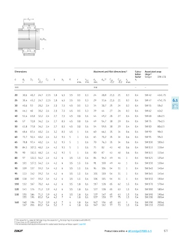
Dimensions Abutment and illet dimensions 1) Calcu- Associated snap
lation rings 2)
factor Seeger DIN 471
d d 1 D 3 C 1 C 2 b b 1 K r r 3,4 d a d 3) C a1 C a2 r a k r
as
≈ +0 2 min min min -0,2 -0,2 max
mm mm – –
20 30,6 40,2 24,7 2,15 1,8 6,5 3,5 0,5 0,3 24 28,8 21,5 21 0,3 0,4 SW 42 42x1 75
25 35,4 45,2 24,7 2,15 1,8 6,5 3,5 0,5 0,3 29 33,6 21,5 21 0,3 0,4 SW 47 47x1 75 6.5
30 40,6 53 28,2 2,4 2,1 7,5 4,5 0,5 0,3 34 38,7 25 24 0,3 0,4 SW 55 55x2
35 46,1 60 30,2 2,4 2,1 7,5 4,5 0,5 0,3 39 44 27 26 0,3 0,4 SW 62 62x2
40 51,4 65,8 32,2 2,4 2,7 7,5 4,5 0,8 0,6 44 49,2 28 27 0,4 0,4 SW 68 68x2 5
45 57 72,8 34,2 2,4 2,7 8,5 4,5 0,8 0,6 49 54,7 30 29 0,4 0,4 SW 75 75x2 5
50 61,8 77,8 34,2 2,4 2,7 8,5 4,5 0,8 0,6 54 59,5 30 29 0,4 0,4 SW 80 80x2 5
55 68,6 87,4 40,2 2,4 3,2 8,5 4,5 1 0,6 60 66,1 35 34 0,6 0,4 SW 90 90x3
60 73,7 92,4 40,2 2,4 3,2 9,5 5 1 0,6 65 71,2 35 34 0,6 0,4 SW 95 95x3
65 78,8 97,4 40,2 2,4 3,2 9,5 5 1 0,6 70 76,3 35 34 0,6 0,4 SW 100 100x3
70 84,5 107,1 48,2 2,4 4,2 9,5 5 1 0,6 75 82 43 40 0,6 0,4 SW 110 110x4
75 90 112,1 48,2 2,4 4,2 9,5 5 1 0,6 80 87 43 40 0,6 0,4 SW 115 115x4
80 97 122,1 54,2 2,4 4,2 6 3,5 1,5 0,6 86 94,3 49 46 1 0,4 SW 125 125x4
85 101 127,1 54,2 2,4 4,2 6 3,5 1,5 0,6 91 100 49 46 1 0,4 SW 130 130x4
90 109 137 59,2 3,4 4,2 6 3,5 1,5 0,6 96 106 54 51 1 0,4 SW 140 140x4
95 113 142 59,2 3,4 4,2 6 3,5 1,5 0,6 101 110 54 51 1 0,4 SW 145 145x4
100 118 147 59,2 3,4 4,2 6 3,5 1,5 0,6 106 115 54 51 1 0,4 SW 150 150x4
110 132 167 70,2 4,4 4,2 6 3,5 1,8 0,6 117 128 65 62 1,5 0,4 SW 170 170x4
120 141 176 71,2 3,9 4,2 6 3,5 1,8 0,6 127 138 65 63 1,5 0,4 SW 180 180x4
130 151 186 71,2 3,9 4,2 6 3,5 1,8 0,6 137 147 65 63 1,5 0,4 SW 190 190x4
155 196 83,2 5,4 4,2 7 4 1,8 0,6 137 150 77 75 1,5 0,4 SW 200 200x4
140 160 196 71,2 3,9 4,2 7 4 1,8 0,6 147 156 65 63 1 0,4 SW 200 200x4
167 206 83,2 5,4 5,2 7 4 1,8 0,6 147 162 77 73 1,5 0,4 SW 210 210x5
1) The values for C a1 apply for SW snap rings, the values for C a2 for snap rings in accordance with DIN 471
2) Snap rings are not supplied by SKF
3) Recommended shaft abutment diameter for axially loaded bearings † Flange support, page 512
Product data online † skf.com/go/17000-6-5 577