
Page 581 - Rollingbearings
P. 581
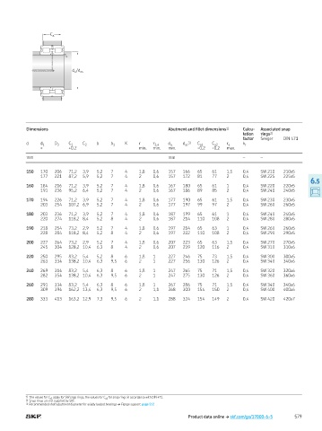
C a


                         r a


                            d a  /  d as


           Dimensions                                          Abutment and illet dimensions 1)  Calcu-  Associated snap
                                                                                           lation   rings 2)
                                                                                           factor  Seeger  DIN 471
           d    d 1  D 3  C 1   C 2  b    b 1  K    r     r 3,4  d a  d 3)  C a1  C a2  r a  k r
                                                                     as
                ≈         +0 2                      min   min   min       -0,2  -0,2  max
           mm                                                  mm                          –     –

           150  170  206  71,2  3,9  5,2  7    4    1,8   0,6  157   166  65   61    1,5   0,4   SW 210   210x5
                177  221  87,2  5,9  5,2  7    4    2     0,6  157   172  81   77    2     0,4   SW 225   225x5
                                                                                                                    6.5
           160  184  216  71,2  3,9  5,2  7    4    1,8   0,6  167   180  65   61    1     0,4   SW 220   220x5
                191  236  95,2  6,4  5,2  7    4    2     0,6  167   186  89   85    2     0,4   SW 240   240x5

           170  194  226  71,2  3,9  5,2  7    4    1,8   0,6  177   190  65   61    1,5   0,4   SW 230   230x5
                203  254  107,2 6,9  5,2  7    4    2     0,6  177   197  99   97    2     0,4   SW 260   260x5

           180  203  236  71,2  3,9  5,2  7    4    1,8   0,6  187   199  65   61    1     0,4   SW 240   240x5
                220  274  118,2 8,4  5,2  8    4    2     0,6  187   214  110  108   2     0,4   SW 280   280x5

           190  218  254  73,2  2,9  5,2  7    4    1,8   0,6  197   214  65   63    1     0,4   SW 260   260x5
                228  284  118,2 8,4  5,2  8    4    2     0,6  197   222  110  108   2     0,4   SW 290   290x5

           200  227  264  73,2  2,9  5,2  7    4    1,8   0,6  207   223  65   63    1,5   0,4   SW 270   270x5
                245  304  128,2 10,4  6,3  8   4    2     0,6  207   239  120  116   2     0,4   SW 310   310x6

           220  250  295  83,2  5,4  5,2  8    6    1,8   1    227   246  75   73    1,5   0,4   SW 300   300x5
                263  334  138,2 10,4  6,3  9,5  6   2     1    227   256  130  126   2     0,4   SW 340   340x6

           240  269  314  83,2  5,4  6,3  8    6    1,8   1    247   265  75   71    1,5   0,4   SW 320   320x6
                282  354  138,2 10,4  6,3  9,5  6   2     1    247   275  130  126   2     0,4   SW 360   360x6

           260  291  334  83,2  5,4  6,3  8    6    1,8   1    267   286  75   71    1,5   0,4   SW 340   340x6
                309  394  162,2 13,4  6,3  9,5  6   2     1,1  268   300  154  150   2     0,4   SW 400   400x6

           280  333  413  163,2 12,9  7,3  9,5  6   2     1,1  288   324  154  149   2     0,4   SW 420   420x7


           1)   The values for C a1  apply for SW snap rings, the values for C a2  for snap rings in accordance with DIN 471
           2)  Snap rings are not supplied by SKF
           3)  Recommended shaft abutment diameter for axially loaded bearings † Flange support, page 512

                                                                       Product data online † skf.com/go/17000-6-5  579