
Page 791 - Rollingbearings
P. 791
Mounting
Table 7
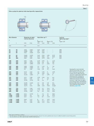
Drive-up data for spherical roller bearings with a tapered bore
s
α
Bore diameter Reduction of radial Axial drive-up 1) 2) Lock nut
internal clearance tightening angle 2)
d s α
Taper 1:12 Taper 1:30 Taper 1:12
> ≤ min max min max min max
mm mm mm °
24 30 0,01 0,015 0,25 0,29 – – 100
30 40 0,015 0,02 0,3 0,35 – – 115
40 50 0,02 0,025 0,37 0,44 – – 130
50 65 0,025 0,035 0,45 0,54 1,15 1,35 115
65 80 0,035 0,04 0,55 0,65 1,4 1,65 130
80 100 0,04 0,05 0,66 0,79 1,65 2 150
100 120 0,05 0,06 0,79 0,95 2 2,35
120 140 0,06 0,075 0,93 1,1 2,3 2,8
140 160 0,07 0,085 1,05 1,3 2,65 3,2
160 180 0,08 0,095 1,2 1,45 3 3,6
180 200 0,09 0,105 1,3 1,6 3,3 4
200 225 0,1 0,12 1,45 1,8 3,7 4,45 Applying the recommended
values prevents the inner ring
225 250 0,11 0,13 1,6 1,95 4 4,85 from creeping, but does not
250 280 0,12 0,15 1,8 2,15 4,5 5,4 ensure correct radial internal
280 315 0,135 0,165 2 2,4 4,95 6 clearance in operation Additional
inluences from the bearing
315 355 0,15 0,18 2,15 2,65 5,4 6,6 housing it and temperature
355 400 0,17 0,21 2,5 3 6,2 7,6 differences between the inner 9
400 450 0,195 0,235 2,8 3,4 7 8,5 and outer rings must be consid-
ered carefully when selecting the
450 500 0,215 0,265 3,1 3,8 7,8 9,5 bearing radial internal clearance
500 560 0,245 0,3 3,4 4,1 8,4 10,3 class (Selecting initial internal
560 630 0,275 0,34 3,80 4,65 9,50 11,60 clearance, page 183)
630 710 0,31 0,38 4,25 5,2 10,6 13
710 800 0,35 0,425 4,75 5,8 11,9 14,5
800 900 0,395 0,48 5,4 6,6 13,5 16,4
900 1 000 0,44 0,535 6 7,3 15 18,3
1 000 1 120 0,49 0,6 6,4 7,8 16 19,5
1 120 1 250 0,55 0,67 7,1 8,7 17,8 21,7
1 250 1 400 0,61 0,75 8 9,7 19,9 24,3
1 400 1 600 0,7 0,85 9,1 11,1 22,7 27,7
1 600 1 800 0,79 0,96 10,2 12,5 25,6 31,2
1) 1) Not valid for the SKF Drive-up Method Not valid for the SKF Drive-up Method
2) 2) The listed values are valid only for solid steel shafts and general applications They are to be used as guideline values only, as it is dificult to establish an exact starting position The listed values are valid only for solid steel shafts and general applications They are to be used as guideline values only, as it is dificult to establish an exact starting position
A
Also, the axial drive-up, s, differs slightly between the different bearings series lso, the axial drive-up, s, differs slightly between the different bearings series
789