
Page 448 - Rollingbearings
P. 448
4 Self-aligning ball bearings
Permissible speed Bearings on sleeves
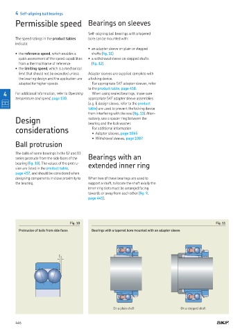
Self-aligning ball bearings with a tapered
The speed ratings in the product tables bore can be mounted with:
indicate:
• an adapter sleeve on plain or stepped
• the reference speed, which enables a shafts (ig. 11)
quick assessment of the speed capabilities • a withdrawal sleeve on stepped shafts
from a thermal frame of reference (ig. 12)
• the limiting speed, which is a mechanical
limit that should not be exceeded unless Adapter sleeves are supplied complete with
the bearing design and the application are a locking device.
adapted for higher speeds For appropriate SKF adapter sleeves, refer
to the product table, page 458.
4 For additional information, refer to Operating When using sealed bearings, make sure
temperature and speed, page 130 appropriate SKF adapter sleeve assemblies
(e.g. E design sleeve, refer to the product
table) are used to prevent the locking device
from interfering with the seal (ig. 13). Alter-
Design natively, use a spacer ring between the
bearing and the lock washer.
considerations For additional information
● Adapter sleeves, page 1065
● Withdrawal sleeves, page 1087
Ball protrusion
The balls of some bearings in the 12 and 13
series protrude from the side faces of the Bearings with an
bearing (ig. 10). The values of the protru- extended inner ring
sion are listed in the product table,
page 457, and should be considered when
designing components in close proximity to When two of these bearings are used to
the bearing. support a shaft, to locate the shaft axially the
inner ring slots must be arranged facing
towards or away from each other (ig. 9,
page 441).
Fig. 10 Fig. 11
Protrusion of balls from side faces Bearings with a tapered bore mounted with an adapter sleeve
C 1
On a plain shaft On a stepped shaft
446