
Page 995 - Rollingbearings
P. 995
Motor encoder units
Permissible speed Motor encoder units in the Motor encoder units with d ≤ 25 mm can
non-locating bearing only be located axially via a snap ring in the
The permissible operating speed is limited position outer ring
by the contact seal in the bearing The sen-
sor can accurately detect speeds from zero SKF recommends using motor encoder units
revolutions per minute up to the limiting in the non-locating bearing position (ig. 9) Motor encoder units in
speed listed in the product table, However, there is a risk that the outer ring loating bearing
page 1002 can spin in the housing bore, especially if arrangements
vibration is a factor Therefore, SKF recom-
mends placing an O-ring in the snap ring When using motor encoder units in loating
groove to help prevent the outer ring from bearing arrangements (page 76), the outer
Design spinning, which could otherwise damage the ring should be prevented from spinning by
considerations cable placing an O-ring in the snap ring groove
The motor encoder unit should be mounted
in such a way that the axial load acts on the
In principle, SKF motor encoder units can be Motor encoder units in the bearing outer ring side face opposite the 17
incorporated in designs in the same way as locating bearing position sensor
SKF deep groove ball bearings Some spe-
ciic recommendations are described below. When using motor encoder units in the
For additional information about electric locating bearing position, the impulse ring,
motor applications, refer to the SKF hand- sensor body and connecting cable should
book Rolling bearings in electric motors and not be subjected to any axial load, whenever
generators. possible When the bearing is subjected to
axial loads that act in both directions, the
motor encoder unit should be mounted in
Cable outlet such a way that the heavier axial load is
transmitted to the bearing outer ring side
The cable emerges radially from the motor face opposite the sensor (ig. 10)
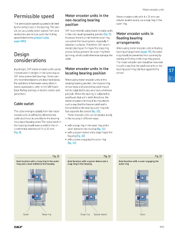
encoder unit. A suficiently dimensioned Motor encoder units can be located axially
cable duct must be provided in the bearing in the housing in different ways:
housing or housing cover. The radial notch in
the housing should have a width in the cir- • with a snap ring in the outer ring and a
cumferential direction of 15 to 20 mm cover bolted to the housing (ig. 11)
(ig. 8) • with a spacer sleeve and a snap ring in the
housing (ig. 12)
• with a cover engaging the outer ring
(ig. 13)
Fig. 11 Fig. 12 Fig. 13
Axial location with a snap ring in the outer Axial location with a spacer sleeve and a Axial location with a cover engaging the
ring and a cover bolted to the housing snap ring in the housing outer ring
Cover Snap ring Snap ring Spacer sleeve Cover
993