
Page 991 - Rollingbearings
P. 991
Motor encoder units
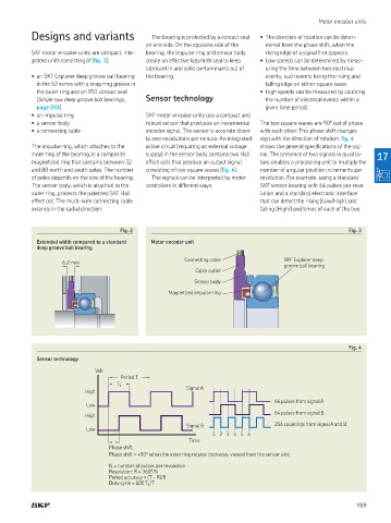
Designs and variants The bearing is protected by a contact seal • The direction of rotation can be deter-
on one side On the opposite side of the mined from the phase shift, when the
SKF motor encoder units are compact, inte- bearing, the impulse ring and sensor body rising edge of a signal irst appears
grated units consisting of (ig. 3): create an effective labyrinth seal to keep • Low speeds can be determined by meas-
lubricant in and solid contaminants out of uring the time between two electrical
• an SKF Explorer deep groove ball bearing the bearing events, such events being the rising and
in the 62 series with a snap ring groove in falling edge on either square wave
the outer ring and an RS1 contact seal • High speeds can be measured by counting
(Single row deep groove ball bearings, Sensor technology the number of electrical events within a
page 241) given time period
• an impulse ring SKF motor encoder units use a compact and
• a sensor body robust sensor that produces an incremental The two square waves are 90° out of phase
• a connecting cable encoder signal The sensor is accurate down with each other This phase shift changes
to zero revolutions per minute An integrated sign with the direction of rotation ig. 4
The impulse ring, which attaches to the active circuit (requiring an external voltage shows the general speciications of the sig-
inner ring of the bearing, is a composite supply) in the sensor body contains two Hall nal The presence of two signals in quadra- 17
magnetized ring that contains between 32 effect cells that produce an output signal ture enables a processing unit to multiply the
and 80 north and south poles The number consisting of two square waves (ig. 4) number of angular position increments per
of poles depends on the size of the bearing The signals can be interpreted by motor revolution For example, using a standard
The sensor body, which is attached to the controllers in different ways: SKF sensor bearing with 64 pulses per revo-
outer ring, protects the patented SKF Hall lution and a standard electronic interface
effect cell The multi-wire connecting cable that can detect the rising (Low/High) and
extends in the radial direction falling (High/Low) times of each of the two
Fig. 2 Fig. 3
Extended width compared to a standard Motor encoder unit
deep groove ball bearing
Connecting cable SKF Explorer deep
6,2 mm
groove ball bearing
Cable outlet
Sensor body
Magnetized impulse ring
Fig. 4
Sensor technology
Volt
Period T
T 1
High Signal A
64 pulses from signal A
Low
64 pulses from signal B
High
Signal B 256 countings from signal A and B
Low
1 2 3 4 5 6
Time
Phase shift
Phase shift = +90° when the inner ring rotates clockwise, viewed from the sensor side
N = number of pulses per revolution
Resolution: R = 360°/N
Period accuracy = (T – R)/R
Duty cycle = 100 T 1 /T
989