
Page 993 - Rollingbearings
P. 993
Motor encoder units
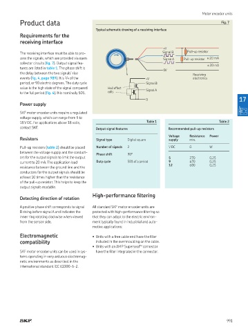
Product data Fig. 7
Typical schematic drawing of a receiving interface
Requirements for the
receiving interface
+ V
The receiving interface must be able to pro- Signal B Pull-up resistor
cess the signals, which are provided via open Signal A Pull-up resistor < 20 mA
collector circuits (ig. 7) Output signal fea-
< 20 mA
tures are listed in table 1 The phase shift is
0 V
the delay between the two signals’ rise Receiving
events (ig. 4, page 989) It is 1 /4 of the + V electronics
period, or 90 electric degrees The duty cycle Signal B
value is the high state of the signal compared Hall effect Signal A
to the full period (ig. 4) It is nominally 50% cells
0 17
Power supply
SKF motor encoder units require a regulated
voltage supply, which can range from 5 to
18 V DC For applications above 18 volts, Table 1 Table 2
contact SKF Output signal features Recommended pull-up resistors
Voltage Resistance Power
Resistors Signal type Digital square supply min
Pull-up resistors (table 2) should be placed Number of signals 2 V DC Ω W
between the voltage supply and the conduct-
Phase shift 90°
ors for the output signals to limit the output 5 270 0,25
current to 20 mA The application load Duty cycle 50% of a period 9 470 0,25
12 680 0,25
resistance between the ground line and the
conductors for the output signals should be
at least 10 times higher than the resistance
of the pull-up resistor This helps to keep the
output signals readable
High-performance iltering
Detecting direction of rotation
A positive phase shift corresponds to signal All standard SKF motor encoder units are
B rising before signal A and indicates the protected with high-performance iltering so
inner ring rotating clockwise when viewed that they can adapt to the electric environ-
from the sensor side ment typically found in industrial and auto-
motive applications:
Electromagnetic • Units with a free cable end have the ilter
compatibility included in the overmoulding on the cable
• Units with an AMP Superseal™ connector
SKF motor encoder units can be used in sys- have the ilter integrated in the connector
tems operating in very arduous electromag-
netic environments as described in the
international standard IEC 61000-6-2
991