
Page 997 - Rollingbearings
P. 997
Motor encoder units
Mounting a unit into a Designation system
housing
Refer to Designation system, page 258.
When motor encoder units have to be The designation preixes and sufixes used
mounted into a housing with an interference to identify motor encoder units are explained
it, they can be pressed into the housing or in the following.
the housing should be heated. The mounting
force should be applied via a mounting Preixes
sleeve or dolly abutting the outer ring side BMB- Motor encoder unit BMB series
face or via a snap ring itted on the outer ring BMD- Motor encoder unit BMD series
(ig. 16). BMO- Motor encoder unit BMO series
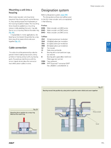
In typical electric motor applications, the
bearing can be moved into position by using Sufixes
bolts to pull the motor shield and cover /032 32 digital pulses per revolution
together (ig. 17). /048 48 digital pulses per revolution
/064 64 digital pulses per revolution 17
/080 80 digital pulses per revolution
Cable connection S2 Two signals
/U Sales area worldwide
The cable should be protected by a duct to A Bearing with a stamped steel cage,
prevent it from making sharp turns, being ball centred
pinched or making contact with any moving B Bearing with a glass ibre reinforced
parts. To avoid any interference with the PA66 cage, ball centred
sensor signal, do not place the connector 008A Free cable end
near other power cables or wires. 108A AMP Superseal™ connector (AMP
Nos 282106-1 and 282404-1)
Fig. 17
Bearing moved into position by using bolts to pull the motor shield and cover together
Fig. 16
Motor shield
Mounting force applied via a snap ring
itted on the outer ring
Cover
995