
Page 1000 - Rollingbearings
P. 1000
17 Sensor bearing units
Sensor technology and higher than the resistance of the pull-up Units for sine wave or vector
electrical data resistor This keeps the output signals control
readable
SKF steering encoder units use sensors to • provide the shaft angle position in real
track the movement of a steering wheel time throughout the entire motor speed
They contain two sets to provide redun- Units providing absolute range
dancy The sensors: position information • provide a signal (diagram 1) comparable
to the one provided by a resolver and can
• are magnetic SKF can provide customized steering units therefore be used by the motor controller’s
• are non-contact and incremental for applications where a combination of software
• do not wear absolute position information, variable • communicate the shaft angle position via a
• are protected from external inluences steering feel, and active end stops are sine/cosine wave signal
• are designed to provide maximum service required For additional information, contact • are more compact and cost-effective than
life SKF inductive resolvers
• are easy to mount (Mounting, page 994)
17 SKF steering encoder units comply with the • do not require special shaft or housing
safety requirements of safety-related control accuracy in comparison with inductive
systems in accordance with ISO 13849 Rotor positioning resolvers (Design considerations,
SKF steering encoder units provide two page 993)
independent sets of square wave signals sensor bearing
(ig. 20) via open collector circuits They SKF can adapt the electronics to comply with
units
require: the interface of the application
• a regulated voltage supply, which can
range from 5 to 24 V DC Synchronous motors require a sensor that
• pull-up resistors (table 2, page 991) that provides the position of the rotor with a high
should be placed between the voltage accuracy, to enable accurate motor torque
supply and the conductors for the output control and to achieve maximum eficiency
signals to limit the output current to and dynamics These motors use either
20 mA direct drive or sine wave control SKF rotor
positioning sensor bearing units (ig. 21,
The application load resistance between the table 5) can contribute to optimized motor
ground line and the conductors for the out- eficiency for both systems
put signals should be at least 10 times
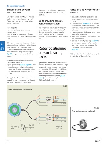
Fig. 20
Sensor technology and electrical data
1
+ V
Signal B Pull-up
2 resistor
Signal A Pull-up < 20 mA
3 resistor
< 20 mA
4
0 V
Fig. 21
Rotor positioning sensor bearing unit
1
+ V
Signal B Pull-up
2 resistor
Signal A Pull-up < 20 mA
3 resistor
< 20 mA
+ V 4 0 V
Signal B
Hall effect Receiving
cells Signal A electronics
0
998