Page 853 - Rollingbearings
P. 853

Design considerations
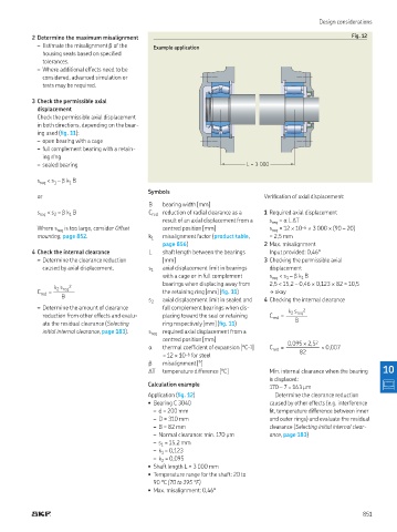
           2 Determine the maximum misalignment                                                           Fig. 12
               – Estimate the misalignment β of the   Example application
              housing seats based on speciied
              tolerances.
               – Where additional effects need to be
              considered, advanced simulation or
              tests may be required.

           3 Check the permissible axial
            displacement
            Check the permissible axial displacement
            in both directions, depending on the bear-
            ing used (ig. 11):
               – open bearing with a cage
               – full complement bearing with a retain-
              ing ring
               – sealed bearing                                            L = 3 000

            s req  < s  – β k  B
                      1
                 1
                                             Symbols
            or                                                                  Veriication of axial displacement:
                                              B   bearing width [mm]
            s req  < s  – β k  B              C red   reduction of radial clearance as a   1 Required axial displacement
                      1
                 2
                                                  result of an axial displacement from a   s req  = α L ΔT
            Where s req  is too large, consider Offset   centred position [mm]    s req  = 12 × 10 –6  × 3 000 × (90 – 20)
            mounting, page 852.               k    misalignment factor (product table,   = 2,5 mm
                                              1
                                                  page 856)                     2 Max  misalignment
           4 Check the internal clearance     L   shaft length between the bearings   Input provided: 0,46°
               – Determine the clearance reduction   [mm]                       3 Checking the permissible axial
              caused by axial displacement.   s 1  axial displacement limit in bearings   displacement
                                                  with a cage or in full complement   s req  < s  – β k  B
                                                                                           1
                                                                                       1
                                                  bearings when displacing away from   2,5 < 15,2 – 0,46 × 0,123 × 82 ≈ 10,5
                 k  s  2
                  2 req
            C red  = ———–                         the retaining ring [mm] (ig. 11)  † okay
                   B
                                              s 2  axial displacement limit in sealed and   4 Checking the internal clearance
               – Determine the amount of clearance   full complement bearings when dis-
                                                                                       k  s  2
                                                                                        2 req
              reduction from other effects and evalu-  placing toward the seal or retaining   C red  = ———–
              ate the residual clearance (Selecting   ring respectively [mm] (ig. 11)    B
              initial internal clearance, page 183).  s req  required axial displacement from a
                                                  centred position [mm]
                                                                                       0,095 × 2,5 2
                                              α   thermal coeficient of expansion [°C –1 ]   C red  = —————– ≈ 0,007
                                                  = 12 × 10 –6  for steel                  82
                                              β   misalignment [°]
                                              ΔT  temperature difference [°C]     Min  internal clearance when the bearing   10
                                                                                  is displaced:
                                             Calculation example                  170 – 7 = 163 μm
                                             Application (ig. 12)                  Determine the clearance reduction
                                             • Bearing C 3040                     caused by other effects (e g  interference
                                                  – d = 200 mm                    it, temperature difference between inner
                                                  – D = 310 mm                    and outer rings) and evaluate the residual
                                                  – B = 82 mm                     clearance (Selecting initial internal clear-
                                                  – Normal clearance: min  170 μm  ance, page 183)
                                                  – s  = 15,2 mm
                                                 1
                                                  – k  = 0,123
                                                 1
                                                  – k  = 0,095
                                                 2
                                             • Shaft length L = 3 000 mm
                                             • Temperature range for the shaft: 20 to
                                               90 °C (70 to 195 °F)
                                             • Max  misalignment: 0,46°


                                                                                                              851
   848   849   850   851   852   853   854   855   856   857   858