Page 852 - Rollingbearings
P. 852

10  CARB toroidal roller bearings
        Temperature                        Cages                              Lubricants
                                           Steel or brass cages can be used at the same   Temperature limits for greases used in
        limits                             operating temperatures as the bearing rings.   sealed CARB bearings are provided in
                                           For temperature limits of polymer cages,   table 1, page 845  For temperature limits of
                                           refer to Polymer cages, page 188.  other SKF greases, refer to Selecting a suit-
        The permissible operating temperature for                             able SKF grease, page 116
        CARB bearings can be limited by:   Seals                                When using lubricants not supplied by
                                                                              SKF, temperature limits should be evaluated
        • the dimensional stability of the bearing   The permissible operating temperature for   according to the SKF trafic light concept
          rings                            seals depends on the seal material:  (page 117)
        • the cage
        • the seals                        • HNBR: –40 to +150 °C (–40 to +300 °F)
        • the lubricant                    • NBR: –40 to +90 °C (–40 to +195 °F)
                                              Temperatures up to 120 °C (250 °F) can   Permissible speed
        Where temperatures outside the permissible   be tolerated for brief periods
        range are expected, contact SKF
                                           Typically, temperature peaks are at the seal   The speed ratings in the product table
        Bearing rings                      lip                                indicate:

        The rings of CARB bearings are heat stabil-                           • the reference speed, which enables a
        ized up to 200 °C (390 °F).                                             quick assessment of the speed capabilities
                                                                                from a thermal frame of reference
                                                                              • the limiting speed, which is a mechanical
                                                                                limit that should not be exceeded unless
                                                                                the bearing design and the application are
                                                                     Fig. 11    adapted for higher speeds
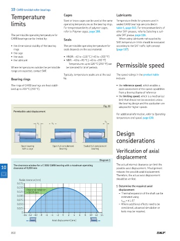
          Permissible axial displacement
                                                                              For additional information, refer to Operating
                                                                              temperature and speed, page 130
                                                                      s 2
                          s 1      s 1

                                                                              Design

                                                                              considerations

               Open bearing         Open full complement    Sealed full complement
                with a cage             bearing              bearing
                                                                              Verification of axial
                                                                              displacement
                                                                   Diagram 1
  10      The clearance window for a C 3052 CARB bearing with a maximum operating    The actual internal clearance can limit the
                                                                              possible axial displacement  Misalignment
          clearance of 0,150 mm
                                                                              reduces the possible axial displacement
                                                                              Therefore, the actual axial displacement
              Radial clearance [mm]                                           should be veriied
            0,175
                                                                              1 Determine the required axial
            0,150
                   Clearance reduction                                          displacement
            0,125  ≈ 0,039 mm
                                                                                   – Thermal expansion of the shaft can be
            0,100                                                                estimated using
            0,075                                                                s req  = α L ΔT
            0,050                                                                 – Where additional effects need to be
            0,025                                                                considered, advanced simulation or
                                                                                 tests may be required
               0
                  –14  –12  –10  –8  –6  –4  –2   0   2   4   6   8   10  12  14
                                    Axial displacement [mm]


        850
   847   848   849   850   851   852   853   854   855   856   857