
Page 514 - Rollingbearings
P. 514
6 Cylindrical roller bearings
Design Mounting
considerations
Because of the design and position of the
cage of high-capacity cylindrical roller bear-
Flange support ings in the NCF ECJB and NJF ECJA
series, the cage cannot prevent the rollers
Where cylindrical roller bearings are sub- from falling out when the inner and outer
jected to axial loads, total axial run-out (Tol- rings of the bearing are separated SKF rec-
erances for bearing seats and abutments, ommends mounting these high-capacity
page 144) and the size of the abutment sur- cylindrical roller bearings as a complete
faces of adjacent components are particu- bearing, like full complement cylindrical
larly important for an even load distribution roller bearings
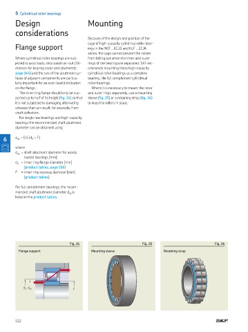
on the lange Where it is necessary to mount the inner
The inner ring lange should only be sup- and outer rings separately, use a mounting
ported up to half of its height (ig. 24) so that sleeve (ig. 25) or a retaining strap (ig. 26)
it is not subjected to damaging alternating to keep the rollers in place
stresses that can result, for example, from
shaft delection
For single row bearings and high-capacity
bearings the recommended shaft abutment
diameter can be obtained using
6 d = 0,5 (d + F)
as
1
where
d = shaft abutment diameter for axially
as
loaded bearings [mm] page 512 footnot
d = inner ring lange diameter [mm]
1
(product tables, page 516)
F = inner ring raceway diameter [mm]
(product tables)
For full complement bearings, the recom-
mended shaft abutment diameter d is
as
listed in the product tables
Fig. 24 Fig. 25 Fig. 26
Flange support Mounting sleeve Retaining strap
d 1 d as F
512