
Page 516 - Rollingbearings
P. 516
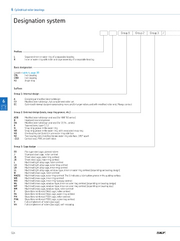
Designation system

        6  Cylindrical roller bearings

          Designation system


                                                                                 Group 1   Group 2  Group 3  /


          Preixes
          L      Separate inner or outer ring of a separable bearing
          R      Inner or outer ring with roller and cage assembly of a separable bearing

          Basic designation

          Listed in table 4, page 30
          CRL    Inch bearing
          CRM    Inch bearing
          HJ     Angle ring

          Sufixes
          Group 1: Internal design
          A      Deviating or modiied internal design
   6      CV     Modiied internal design, full complement roller set
          EC     Optimized internal design incorporating more and/or larger rollers and with modiied roller end / lange contact


          Group 2: External design (seals, snap ring groove, etc.)
          ADB    Modiied internal design and seal (for NNF 50 series)
          B      Improved seal and grease
          DA     Modiied internal design and seal (for 3194‥ series)
          K      Tapered bore, taper 1:12
          N      Snap ring groove in the outer ring
          NR     Snap ring groove in the outer ring, with associated snap ring
          N1     One locating slot (notch) in one outer ring side face
          N2     Two locating slots (notches) in one outer ring side face, 180° apart
          -2LS   Contact seal, PUR, on both sides

          Group 3: Cage design
          FR     Pin-type steel cage, pierced rollers
          J      Stamped steel cage, roller centred
          JA     Sheet steel cage, outer ring centred
          JB     Sheet steel cage, inner ring centred
          L      Machined light alloy cage, roller centred
          LA     Machined light alloy cage, outer ring centred
          LB     Machined light alloy cage, inner ring centred
          LL     Machined light alloy cage, window-type, inner or outer ring centred (depending on bearing design)
          M      Machined brass cage, roller centred
          MA(S)  Machined brass cage, outer ring centred. The S indicates a lubrication groove in the guiding surface.
          MB     Machined brass cage, inner ring centred
          MH     Machined brass cage, inner ring raceway centred
          ML     Machined brass cage, window-type, inner or outer ring centred (depending on bearing design)
          MP     Machined brass cage, window-type, inner or outer ring centred (depending on bearing size)
          MR     Machined brass cage, window-type, roller centred
          P      Glass ibre reinforced PA66 cage, roller centred
          PA     Glass ibre reinforced PA66 cage, outer ring centred
          PH     Glass ibre reinforced PEEK cage, roller centred
          PHA    Glass ibre reinforced PEEK cage, outer ring centred
          V      Full complement of rollers (no cage)
          VH     Full complement of rollers (no cage), self-retaining


        514