
Page 1099 - Rollingbearings
P. 1099
Designs and variants
The locking principle Precision lock nuts Features and beneits
with axial locking • Maximum axial run-out between the
KMT and KMTA series precision lock nuts locating face and thread: 0,005 mm
have three locking pins equally spaced screws • Adjustable for precise axial positioning
around their circumference (ig. 19 to • Effective locking prevents the nut from
ig. 21) that can be tightened with grub KMD lock nuts (ig. 23) were designed specif- loosening under normal operating
screws to lock the nut onto the shaft The ically for screw compressors but can be used conditions
end face of each pin is machined to match in other applications where high precision, • Simple installation and removal
the shaft thread The holes for the locking simple assembly and reliable locking are • No keyway required
pins and grub screws are drilled with their required Once the four locking screws are • Reusable
axis parallel to the loaded lanks of the shaft tightened, the lock nut will be accurately • Designed for frequent installation and
thread (ig. 22) The locking screws, when positioned at right angles to the shaft thread removal
tightened to the recommended torque, pro- The locking screws, when tightened to the
vide suficient friction between the ends of recommended tightening torque, preload These lock nuts are not listed in this cata-
the pins and the unloaded thread lanks to the lock nut and shaft threads and generate logue, but can be found online at
prevent the nut from loosening under nor- suficient friction to prevent the nut from skf com/go/17000-25-6
mal operating conditions (Loosening torque, loosening under normal operating condi-
page 1098) Because the locking pins are tions The locking screws do not carry any
tightened against the unloaded lanks of the part of the supported load in service The locking principle
shaft thread, they are not subjected to any KMD lock nuts are available for thread
application loads imposed on the nut M 20x1 to M 105x2 (sizes 4 to 21) KMD lock nuts are locked with axial locking
screws (ig. 24) The front of the lock nut
locates the component on the shaft The rear
is tightened against the unloaded lanks of
the shaft thread by axial locking screws,
creating suficient friction to prevent the lock
nut from loosening under normal operating
conditions
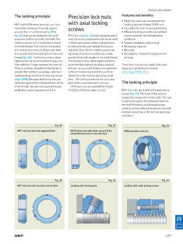
Fig. 19 Fig. 21 Fig. 23
KMT lock nut with two opposed lats KMTA lock nuts with holes around their KMD precision lock nut
circumference and in one side face
Fig. 20 Fig. 22 Fig. 24
KMT lock nut with six slots and no lats Locking with locking pins Locking with axial locking screws
25
1097