
Page 1104 - Rollingbearings
P. 1104
25 Lock nuts
Precision lock nuts Adjustment
with locking pins Precision lock nuts with locking pins are
adjustable The three equally-spaced locking
KMT precision lock nuts have slots around pins enable these lock nuts to be accurately
their circumference to accommodate a hook positioned at right angles to the shaft How-
or impact spanner (ig. 19, page 1097, and ever, they can also be adjusted to compen-
ig. 20, page 1097) The designations of the sate for slight angular deviations of adjacent
associated spanners are listed in the prod- components
uct table, page 1114 KMT precision lock Adjustments can be made using the fol-
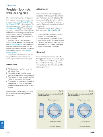
nuts with a thread ≤ 75 mm (sizes ≤ 15) have lowing procedure (ig. 31 and ig. 32):
additionally to the slots two opposed lats to
accommodate a spanner Those lock nuts 1 Loosen the grub screw(s) at the position
with a thread ≥ 80 mm (sizes ≥ 16) have six showing the greatest deviation
slots and no lats 2 Tighten the remaining screw(s) equally
KMTA precision lock nuts have holes 3 Retighten the screw(s) that were loosened
around their circumference and in one side 4 Check that the alignment of the nut, rela-
face (ig. 21, page 1097) They can be tight- tive to the shaft, is currently as required
ened with a pin wrench or a pin-type face 5 Repeat the procedure if necessary
spanner Associated spanners in accordance
with DIN 1810 are listed in the product
table, page 1116 Removal
Precision lock nuts with locking pins are
designed for frequent installation and When removing precision lock nuts with
removal, provided they are not damaged locking pins, the locking pins can still engage
the shaft thread even after the grub screws
have been loosened Using a rubber ham-
Installation mer, tap the nut lightly in the vicinity of the
pins to loosen them
1 With the bearing in position, screw the
lock nut into place
2 Tighten the nut with a hook or impact
spanner making sure not to over tighten it
3 Tighten the grub screws carefully until the
locking pins engage the shaft thread
4 Tighten the grub screws alternately with a
torque wrench until the recommended
torque value, listed in the product tables, is
achieved
Precision lock nuts with locking pins should Fig. 31 Fig. 32
not be used to drive a bearing up onto a Example 1: Adjustment procedure for KMT Example 2: Adjustment procedure for KMT
tapered seat and KMTA lock nuts and KMTA lock nuts
Retighten grub screw Retighten grub screws
*) *)
* Loosen grub screws *
25 Loosen grub screw
*) Greatest deviation *) Greatest deviation
1102