
Page 1098 - Rollingbearings
P. 1098
25 Lock nuts
Precision lock nuts KMTA lock nuts (ig. 17): Features and beneits
with locking pins • are available for thread M 25x1,5 to • Maximum axial run-out between the
locating face and thread (sizes ≤ 40):
M 200x3 (sizes 5 to 40) 0,005 mm
KMT and KMTA lock nuts are intended for • have a cylindrical outside surface and, for • Adjustable to compensate for slight angu-
applications where high precision, simple some sizes, a different thread pitch than lar deviations (ig. 18)
assembly and reliable locking are required 1) KMT lock nuts • Fine thread pitch
The three equallyspaced locking pins • are intended primarily for applications • Withstands high axial loads
enable these lock nuts to be accurately posi where space is limited and the cylindrical • Reliable, effective locking mechanism
tioned at right angles to the shaft However, outside surface can be used as an element • Simple installation and removal
they can also be adjusted to compensate for of a gap-type seal • No keyway required 1)
slight angular deviations of adjacent • Reusable
components • Designed for frequent installation and
removal
KMT lock nuts (ig. 16):
• are available for thread M 10x0,75 to
M 200x3 (sizes 0 to 40)
• are available on request for thread
Tr 220x4 to Tr 420x5 (sizes 44 to 84)
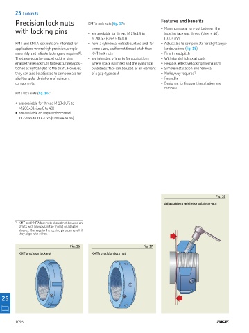
Fig. 18
Adjustable to minimise axial run-out
1) KMT and KMTA lock nuts should not be used on
shafts with keyways in the thread or adapter
sleeves Damage to the locking pins can result if
they align with either
Fig. 16 Fig. 17
KMT precision lock nut KMTA precision lock nut
25
1096