
Page 372 - SKF-bearing-housings
P. 372
Split plummer block housings SONL series
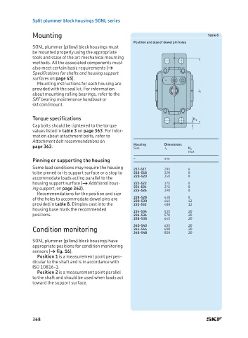
Mounting Table 8
Position and size of dowel pin holes
SONL plummer (pillow) block housings must
be mounted properly using the appropriate
tools and state of the art mechanical mounting
methods. All the associated components must
also meet certain basic requirements (†
Specifications for shafts and housing support
surfaces on page 45).
Mounting instructions for each housing are
provided with the seal kit. For information J 6
about mounting rolling bearings, refer to the
SKF bearing maintenance handbook or
skf.com/mount.
Torque specifications N 4
Cap bolts should be tightened to the torque
values listed in table 3 on page 363. For infor-
mation about attachment bolts, refer to
Attachment bolt recommendations on
page 363. Housing Dimensions N 4
Size
J 6
max
Pinning or supporting the housing – mm
Some load conditions may require the housing 217-517 290 6
to be pinned to its support surface or a stop to 218-518 320 8
accommodate loads acting parallel to the 220-520 350 8
housing support surface († Additional hous- 222-522 370 8
ing support, on page 362). 224-524 370 8 8
226-526
390
Recommendations for the position and size
of the holes to accommodate dowel pins are 228-528 430 8 12
460
230-530
provided in table 8. Dimples cast into the 232-532 480 12
housing base mark the recommended 234-534 530 20
positions. 236-536 570 20
238-538 640 20
240-540 630 20
Condition monitoring 244-544 690 20
248-548 800 20
SONL plummer (pillow) block housings have
appropriate positions for condition monitoring
sensors († fig. 16).
Position 1 is a measurement point perpen-
dicular to the shaft and is in accordance with
ISO 10816-1.
Position 2 is a measurement point parallel
to the shaft and should be used when loads act
toward the support surface.
368