
Page 613 - Rollingbearings
P. 613
Mounting
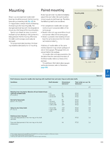
Mounting Paired mounting Fig. 42
Mounting dolly
If bearings are to be mounted immediately
Drawn cup and alignment needle roller adjacent to each other, the load should be
bearings should be pressed into the housing shared equally by both bearings. Therefore,
bore using a mounting dolly (ig. 42) An the following need to be considered:
O-ring provides a simple means of retaining
the bearing on the mounting dolly The • Full complement needle roller arrange- 15°
stamped side (side face with the designation) ments should incorporate rollers of the
should abut the lange of the mounting dolly. same gauge.
Special care should be taken to prevent • Needle roller and cage assemblies should
the bearing from skewing or tilting when it is incorporate rollers of the same gauge
being pressed into the housing. Otherwise • Drawn cup needle roller bearings should
the rollers and raceways could easily be have the same deviations from the nomi-
damaged. nal inside diameter F . –0,2
w
For grease lubricated bearings, the bear- D –0,3
ing should be lubricated prior to mounting. A delivery of needle rollers of the same
nominal diameter may contain packages of
one or more gauges. The gauge limits are
also printed on the package.
For needle roller and cage assemblies, the
deviation from the nominal dimensions of
the itted needle rollers is printed on the
package
F w –0,025
For additional information about gauges
and inside diameter, refer to Tolerances,
page 598
7
Table 18
Shaft tolerance classes for needle roller bearings with machined inner and outer rings on solid steel shafts
Conditions Shaft diameter Dimensional Total radial run-out Ra
tolerance 1) tolerance 2)
– mm – – µm
Rotating inner ring load or direction of load indeterminate
Light and variable loads ≤ 10 k5 IT5/2 0,4
(P ≤ 0,05 C) > 10 to 25 k6 IT5/2 0,8
> 25 to 100 m6 IT5/2 0,8
Normal to heavy loads ≤ 25 k5 IT5/2 0,4
(0,05 C < P ≤ 0,1 C) > 25 to 60 m6 IT5/2 0,8
> 60 to 100 n6 IT5/2 0,8
> 100 to 400 p6 3) IT5/2 1,6
Heavy to very heavy loads > 50 to 100 n6 3) IT5/2 0,8
(P > 0,1 C) > 100 to 200 p6 3) IT5/2 1,6
> 200 r6 3) IT5/2 1,6
Stationary inner ring load
Easy axial displacement of the inner ring on the shaft g6 IT5/2 1,6
desirable
Easy axial displacement of the inner ring on the shaft h6 IT5/2 1,6
unnecessary
1) The envelope requirement (symbol � from ISO 14405-1) is not shown but applies to all tolerance classes
2) Values listed are for bearings to Normal tolerances
3) Bearings with radial internal clearance greater than Normal may be necessary
611