
Page 611 - Rollingbearings
P. 611
Design considerations
Design For less demanding applications, snap rings Combined needle roller bearings
can be used Otherwise, use an intermediate The diameter of the thrust bearing support
considerations ring, e g a spring steel washer, between the surface in the housing should be at least
snap ring and the cage assembly 0,5 mm larger than the dimension D or D
1
2
(ig. 41 and product tables of Needle roller /
For general information, refer to Bearing Needle roller bearings with thrust ball bearings, page 656, and Needle
interfaces, page 140 roller / cylindrical roller thrust bearings,
machined rings, without langes
page 658)
Appropriate abutment diameters are listed
in the product tables
Abutment Recommendations for surfaces of adja-
dimensions cent machine components that guide the
cage of needle roller bearings without
langes axially:
Needle roller and cage assemblies
• ine turned and polished
Appropriate abutment diameters are pro- • hardened and ground for high-speed
vided in table 15 operations
Recommendations for surfaces of adja- • no interruptions
cent machine components that guide needle
roller and cage assemblies axially: For less demanding applications, snap rings
can be used Otherwise, use an intermediate
• ine turned and polished ring, e g a spring steel washer, between the
• hardened and ground for high-speed snap ring and the cage assembly
operations
• no interruptions
7
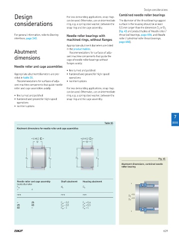
Table 15
Abutment dimensions for needle roller and cage assemblies
U H12 � U H12 �
U U
d a E w D a F w Fig. 41
Abutment dimensions, combined needle
roller bearing
Needle roller and cage assembly Shaft abutment Housing abutment
Inside diameter
F w d a D a
> ≤
mm mm mm +0,5
D 1
+0,5
D 2
– 25 E w – 0,3 F + 0,4
w
25 65 E – 0,5 F w + 0,5
w
65 – E – 1 F w + 1
w
609