
Page 469 - SKF-bearing-housings
P. 469
Design considerations
Additional housing support modate the loads acting parallel to the support
When the housing is subjected to loads acting surface.
parallel to the support surface, it may be nec-
essary to pin the housing to the support sur-
face or to provide a stop to counter the load.
When loads act at angles between 60° and
120°, or when the axial loads are greater than
5% of P 180° , the housing should be pinned to
the support surface or a stop should be pro-
vided to counter the load. The dowel pins or
stop should be sufficiently strong to accom-
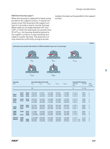
Table 5
Safe loads and cap bolt information for SDAF extended range cast iron housings
P 60° P 90° P 120°
9
P 150° P 180°
Housing Recommended safe loads Cap bolt information
Size P 60° P 90° P 120° P 150° P 180° Cap bolt Torque SAE
size grade
– lbf. in. ft.-lbs.
3152 3248 294 000 17 600 110 000 98 000 118 000 1.1/2-6 1950 5
3060 3156 3252 408 000 245 000 156 000 143 000 176 000 1.1/2-6 1950 5
3064 3160 3256 408 000 245 000 156 000 143 000 176 000 1.1/2-6 1950 5
3068 3160 3256 408 000 245 000 156 000 143 000 176 000 1.1/2-6 1950 5
3072 3164 3260 442 000 265 000 170 000 153 000 186 000 1.3/4-5 2280 5
3076 442 000 265 000 170 000 153 000 186 000 1.3/4-5 2280 5
3168 3264 517 000 310 000 200 000 186 000 228 000 1.7/8-5 2860 5
3080 3172 3268 650 000 390 000 245 000 224 000 275 000 1.3/4-5 2280 5
3084 3176 650 000 390 000 245 000 224 000 275 000 1.3/4-5 2280 5
3088 3180 3272 717 000 430 000 275 000 250 000 305 000 1.7/8-5 2860 5
3092 3276 717 000 430 000 275 000 250 000 305 000 1.7/8-5 2860 5
3096 3184 3280 1 050 000 630 000 405 000 375 000 465 000 2-4.1/4 3440 5
30/500 3188 1 050 000 630 000 405 000 375 000 465 000 2-4.1/4 3440 5
30/530 3192 3284 900 000 540 000 345 000 320 000 400 000 2.1/4-4.1/2 5030 5
3196 3288 900 000 540 000 345 000 320 000 400 000 2.1/4-4.1/2 5030 5
465