
Page 972 - Rollingbearings
P. 972
16 Cam followers
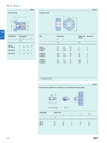
Table 2 Table 3
Grease ittings Hexagonal nuts
m s
L
L 1
e
D M 1
16
Designation Dimensions Size Dimensions Tightening Standard 1)
M 1 D L L 1 torque
m e s
– mm
– mm Nm –
NIP A1 4 6 6 1,5
NIP A1x4,5 4 4,7 4,5 1 M 6x1 5,2 11 10 3 1
M 8x1,25 6,8 14,4 13 8 1
NIP A2x7,5 6 7,5 7,5 2 M 10x1 8,4 17,8 16 15 2
NIP A3x9,5 8 10 9,5 3 M 12x1,5 10,8 20 18 22 2
M 16x1,5 14,8 26,8 24 58 2
M 18x1,5 15,8 29,6 27 87 2
M 20x1,5 18 33 30 120 2
M 24x1,5 21,5 39,5 36 220 2
M 30x1,5 25,6 50,9 46 450 2
1) 1 = EN ISO 4032, ISO 4032
2 = EN ISO 8673, ISO 8673
Table 4
Dimensions of adapters for connecting to a centralized lubrication system
L 2
SW
L 1 L a
L
AP 8 and AP 10 AP 14
Designation Dimensions
L L 1 L 2 L a SW
– mm
AP 8 27 22 4 16 8
AP 10 27 22 5 15 10
AP 14 25 20 6 8 14
970