
Page 692 - Rollingbearings
P. 692
8 Tapered roller bearings
Mounting Load zone
In the majority of rolling mill applications,
Double row tapered the direction of a radial load is constant.
roller bearings Depending on the ratio between axial and
radial loads, usually only approximately one
quarter of the outer ring raceway is under
Depending on their design, components of load. Therefore (ig. 23):
double row tapered roller bearings can also
be mounted separately. The individual rings • Outer rings are divided into four zones
of one bearing must be mounted in the cor- identiied by a marking I to IV on the outer
rect order and position. They must also not ring side faces, on request
be mixed with those of another bearing • Markings for zone I are also joined by a
when several bearings are mounted at the line across the outside surface
same time. Therefore, some precautions • For initial mounting, zone I (line across the
have been taken to ease mounting: outside surface) should be positioned in
the direction of the load
• Components of one bearing are marked • Depending on the operating conditions,
with letters that indicate their correct after a period of service the outer rings
order and position (ig. 22). should be turned through 90° so that a
• All components of one bearing are marked new (the next) zone becomes the loaded Fig. 22
with the same serial number. zone. Components are marked with letters that
indicate their correct order and position
Special care should be taken not to deform
or compress the relatively thin-walled inter-
mediate rings when mounting smaller TDI
design bearings. This can happen, for ex -
ample, when tightening the cover screws
and can have a negative impact on the axial A B
clearance or the preload. Therefore, SKF A B
recommends applying a cover with a centring
spigot that is appropriate to the widths of the
8 bearing and the housing seat. A B
If the knowledge and experience required
to mount double row tapered roller bearings
A B
is unavailable, especially where large bear-
ings are concerned, SKF recommends that
the assistance of SKF service personnel be
requested. Further details of the SKF
mounting service are available on request.
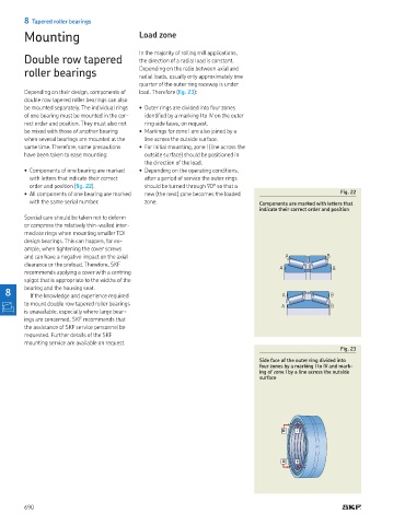
Fig. 23
Side face of the outer ring divided into
four zones by a marking I to IV and mark-
ing of zone I by a line across the outside
surface
690