Page 688 - Rollingbearings
P. 688

8  Tapered roller bearings
        Permissible speed


        The speed ratings in the product tables
        indicate:

        • the reference speed, which enables a
          quick assessment of the speed capabilities
          from a thermal frame of reference
        • the limiting speed, which is a mechanical
          limit that should not be exceeded unless
          the bearing design and the application are
          adapted for higher speeds

        For additional information, refer to Operating
        temperature and speed, page 130.
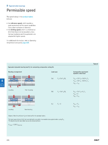


                                                                                                        Table 8
                                   for calculating comparative rating life
          Equivalent dynamic bearing load P F

          Bearing arrangement                             Load case               Comparative equivalent
                                                                                  dynamic radial load

                 F r              F r
                                                          1a)   F  ≤ 0,6 F rL /K L  P FL1  = 0,5 F rL + 0,83 K L  F a
                                                                 a
   8                                                                              P FL2  = 0,5 F rL - 0,83 K L  F a
                                                                                  P FN   = F rN
                      F a
             1       2
          Locating           Non-locating
                                                          1b)   F  > 0,6 F /K L   P FL1  = 0,4 F + K  F
                                                                 a
                                                                                          rL
                                                                                             L a
                                                                       rL
                                                                                  P FL2  = 0
                                                                                  P   = F rN
                                                                                   FN
                 F r              F r
                                                          1c)   F a  = 0
                      F a                                                         P FL1  = F rL
                                                                                  P   = F
               1  2                                                                FN  rN
          Locating          Non-locating


          Values of the thrust factor K L are listed as K in the product tables.
          For load cases 1a) and 1b), the load rating for one roller row needs to be applied when using P FL .
          The load rating for one roller row can be obtained from

          C F(row)  = 0,58 C F(bearing)


        686
   683   684   685   686   687   688   689   690   691   692   693