Page 686 - Rollingbearings
P. 686

8  Tapered roller bearings
        Matched bearings arranged
        back-to-back


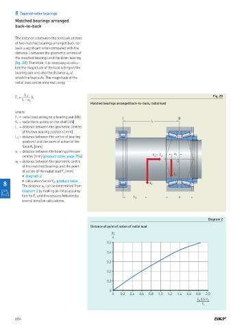
        The distance a between the pressure centres
        of two matched bearings arranged back-to-
        back is signiicant when compared with the
        distance L between the geometric centres of
        the matched bearings and the other bearing
        (ig. 20)  Therefore, it is necessary to calcu-
        late the magnitude of the load acting on the
        bearing pair and also the distance a  at
                                  1
        which the load acts. The magnitude of the
        radial load can be obtained using:


             L 1
        F  = JKK K r                                                                                    Fig. 20
         r
            L – a 1
                                             Matched bearings arranged back-to-back, radial load
        where
        F  = radial load acting on a bearing pair [kN]      !                          !!
         r
        K  = radial force acting on the shaft [kN]                        L
         r
        L  =  distance between the geometric centres
            of the two bearing positions [mm]
        L  =  distance between the centre of bearing
         1
            position I and the point of action of the
            force K  [mm]
                 r
        a  =  distance between the bearing pressure
                                                                             =       a 1
            centres [mm] (product table, page 754)                         K a  F a
        a  =  distance between the geometric centre                                    0
         1
            of the matched bearings and the point
            of action of the radial load F  [mm]
                                r
            • diagram 2                                                              F r
            • calculation factor Y , product table
   8        The distance a  can be determined from                       K r
                           2
                      1
            diagram 2 by making an initial assump-
            tion for F  and if necessary followed by              L 1                  a
                  r
            several iterative calculations.


                                                                                                      Diagram 2
                                             Distance of point of action of radial load
                                                       a 1
                                                       —
                                                       a
                                                     0,5

                                                     0,4
                                                     0,3

                                                     0,2

                                                     0,1

                                                      0
                                                       0   0,2  0,4  0,6  0,8  1,0  1,2  1,4  1,6  1,8  2,0
                                                                                                F a  1,5 Y 2
                                                                                                
                                                                                                   F r

        684
   681   682   683   684   685   686   687   688   689   690   691