
Page 777 - Rollingbearings
P. 777
Designs and variants
Designs and CC, CA and E design • are indicated in the product table by the
designation sufix CA
variants bearings • are indicated in the product table by the
designation sufix ECA for larger bearings
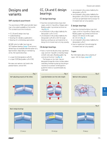
CC design bearings and have an optimized internal design for
SKF standard assortment increased load carrying capacity
• have two stamped window-type steel
The assortment of SKF spherical roller bear- cages, an inner ring without langes and a E design bearings
ings is the widest available on the market loating guide ring centred on the inner
The standard assortment includes: ring (ig. 6) • have two stamped window-type steel
• are indicated in the product table by the cages, an inner ring without langes and a
• CC, CA and E design bearings designation sufix C or CC loating guide ring centred on the inner
• sealed bearings • are indicated in the product table by the ring (d ≤ 65 mm) or on the cages
• bearings for vibratory applications designation sufix EC or ECC for larger (d > 65 mm) (ig. 6)
• bearings for wind energy applications bearings and have an optimized internal • are indicated in the product table by the
design for increased load carrying capacity designation sufix E
All SKF spherical roller bearings are • have an optimized internal design for
SKF Explorer bearings (page 7) and almost CA design bearings increased load carrying capacity
all bearings are available with the option of a
tapered bore Depending on the bearing • have a machined double prong-type brass Cages
series, the tapered bore has: cage, an inner ring with a retaining lange
on both sides and a loating guide ring For information about the suitability of
• a taper 1:12 (designation sufix K) centred on the inner ring (ig. 6) cages, refer to Cages, page 187.
• a taper 1:30 (designation sufix K30) The langes on the inner ring are
designed to keep the rollers in place when
For sizes and variants not listed in the swivelling the bearing during mounting or
product tables, contact SKF. maintenance and are not designed to
guide the rollers or accommodate any
axial load.
Fig. 3 Fig. 4 Fig. 5
Self-adjusting property of the rollers Load distribution over the roller length Optimal roller guidance
9
Fig. 6
Basic design bearings
CC design CA design E design
775