
Page 595 - Rollingbearings
P. 595
Designs and variants
Needle roller bearing IR series inner rings Needle rollers
components • are the standard SKF inner rings for nee- Needle rollers can be used to design full
dle roller bearings
• are hardened and ground complement bearing arrangements for low-
Needle roller bearing inner • have a precision ground raceway surface speed or oscillating applications These com-
rings with a lead-in chamfer on both sides pact bearing arrangements have a very high
The chamfers facilitate assembly and load carrying capacity when compared to
SKF supplies inner rings for needle roller protect the seal lips from damage during bearings with a cage and are economical,
bearings separately They are typically com- the mounting process provided the shaft and housing bore can
bined with needle roller and cage assemblies • are available in some sizes with a lubrica- serve as raceways (Raceways on shafts and
(page 583) or drawn cup needle roller bear- tion hole (designation sufix IS1, ig. 36) in housings, page 179)
ings (page 584) in applications where the Inner rings with additional lubrication Needle rollers:
shaft cannot be hardened and ground holes are available on request
Inner rings are available in two series • are available on request with a pre-ground • are not listed in this catalogue, but can be
(ig. 35): raceway and a machining allowance found online at skf com/go/17000-7-12
(designation sufix VGS, table 2) • are made of carbon chromium steel
• IR series They can be inish ground after mount- • have a hardness of 58 to 65 HRC
– with or without a lubrication hole ing on a shaft in applications where • have a precision ground surface
– with or without a machining allowance extremely tight geometrical tolerances are
• LR series required For assistance in designing full complement
bearing arrangements or to calculate per-
Both inner ring series: LR series inner rings formance data for these bearing arrange-
ments, contact the SKF application engi-
• are also available in different widths • are hardened, and the bore and raceway neering service.
• permit greater axial displacement of the diameter are ground
shaft, relative to the housing, when they • side faces are turned and the edges are
are wider than standard smoothed
– provide an excellent counterface for the • can be used to provide a cost-effective
lips of contact seals (ig. 12, page 586) bearing arrangement for applications 7
• should be located on both sides to prevent where the larger run-out and width toler-
axial movement (regardless of whether ances are less important
the ring has an interference or loose it)
– one side can be located against a
shoulder
– the other side can be located by either a
snap ring, a distance ring or a nut
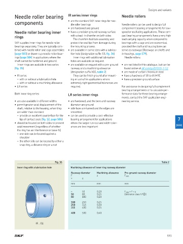
Fig. 36 Table 2
Inner ring with a lubrication hole Machining allowance of inner ring raceway diameter
Raceway diameter Machining allowance Pre-ground raceway diameter
F z F VGS
> ≤
mm mm mm
– 50 0,10 F VGS = F + z
50 80 0,15 (tolerance class h7�)
80 180 0,20
180 250 0,25
250 315 0,30
315 400 0,35
400 500 0,40
IR ‥ IS1
593